Introduction to LEDs
LED stands for Light Emitting Diode, a semiconductor device that emits light when an electric current passes through it. The first visible-spectrum LED was developed in 1962 by Nick Holonyak Jr. at General Electric. Initially, these LEDs could only produce red light, and they were used as indicator lamps in electronic devices.
Over the years, researchers developed LEDs capable of emitting different colors, including green, yellow, and blue. The blue LED, invented by Shuji Nakamura in the 1990s, was a breakthrough that paved the way for white LEDs and revolutionized the lighting industry.
Construction and Working Principle
An LED is a semiconductor device that consists of a p-n junction, which is formed by combining a p-type semiconductor material (with an excess of holes) and an n-type semiconductor material (with an excess of electrons).
This is the same material that our trusty MOSFET is made of. The only difference is that MOSFET has a p-n-p or n-p-n sandwitch.
When a forward bias voltage is applied across the p-n junction, electrons from the n-type material are injected into the p-type material, and holes from the p-type material are injected into the n-type material. These electrons and holes recombine, releasing energy in the form of photons, which we perceive as light.
Of course this is a simplistic view of what is happening and especially for the blue LEDs there are a lot more nuances.
Appearance
Through-Hole LEDs
Through-hole LEDs are a common type of LED package that has two leads protruding from the bottom, allowing them to be inserted into holes on a circuit board for soldering. These LEDs are often cylindrical in shape and come in various sizes.
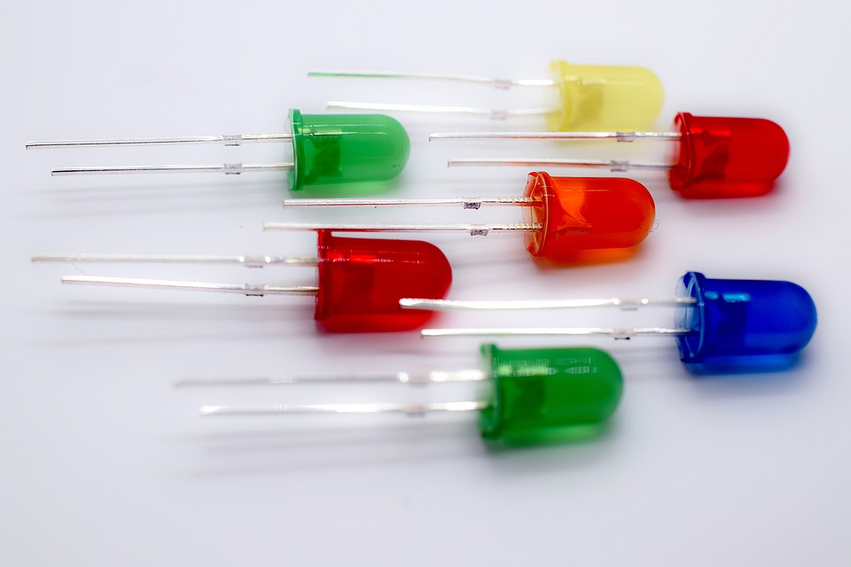
The longer lead is typically the anode (positive terminal), while the shorter lead is the cathode (negative terminal). It's essential to connect the LED correctly in the circuit, as reversing the polarity can damage it.
This is the type I used to construct my processor.
Connecting LEDs in a Circuit
LEDs are not like regular light bulbs and cannot be connected directly to a voltage source. Due to their low resistance, they require a current-limiting resistor in series to prevent excessive current flow, which could damage the LED.
In the circuit above, the LED is connected in series with a 150-ohm resistor to limit the current flowing through it. The resistor value is chosen based on the LED's forward voltage drop and the supply voltage to ensure safe operation.
In the case of red LED, the voltage drop is 2V and the safe current to pass through it is 20mA. So if we wanted to use 5V power source (USB power input) we need something to limit the current and drop the voltage.
Since we want to limit the current through the LED we need to make a series circuit. This is because in parallel arangement we cannot influence the current in one branch by doing something in the other. But we can do that in the series configuration.
So the voltage drop on the resistor and the LED should add up to 5V (input voltage) and their current should be the same.
    5V = Uled + Uresistor
    I = Iled_forwrad = Iresistor
From the LED datasheet we know that Iled_forward is 20mA and Uled = 2V:
    5V = 2V + Uresistor => Uresistor = 3V
    20mA = Iresistor
We have the voltage drop on the resistor and the current that we want to pass through it, so we can get the resistance using Ohm's law:
    R = Uresistor/Iresistor
    R = 3V / 20mA
    R = 150 ohm
The real resistor value
Now the fancy calculation above is correct but that is not the value I used in the processor. I wanted to power the processor through USB and power supply in Arduino but even if I had only 100 LEDs that would be 20mA * 100 = 2A of current.
Even if we assume that only half of them will be turned on at each time that is still 1A, far above the Arduino power supply and regular USB laptop/computer ports.
Now if I use some independent power supply I still need to distribute the power through the processor and make some lines wider. This all assumes we need 20mA for LED to run. While that is a safe limit to run the LED which lets it be the brightest, we do not need it to be that bright. Human vision is logarithmic, 10 times brighter object does not look 10 times brighter to us:
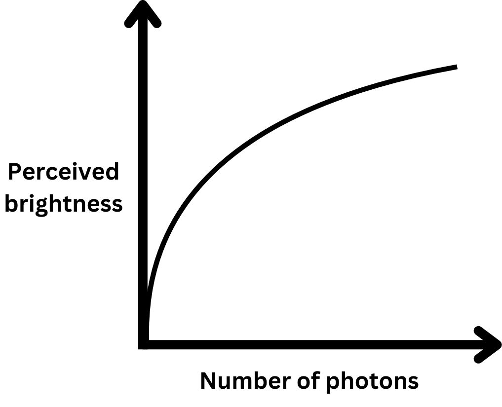
As you can see in the far right, substantial decrease in number of photons (light particles) does not yield that big of a perceived brightness loss.
I did some testing and current as low as 1mA was producing visible results. In the end I decided to go with 3mA which gave me enough bang for my buck, was visible and not a lot of power was being used. So the final resistor value is thus:
    R = Uresistor / Ivisible_LED_current
    R = 3V / 3mA
    R = 1000 ohm
LED Characteristics
So just as we did with the MOSFET lets go through some characteristics of LEDs. I already mentioned all of them, voltage drop and forward current, but lets repeat and expand.
Voltage Drop
Unlike resistors, which follow Ohm's law, LEDs have a non-linear voltage-current relationship. They exhibit a constant voltage drop across their terminals, known as the forward voltage drop, typically ranging from 1.8V to 3.3V, depending on the LED's color and material.
To light up an LED, the applied voltage must exceed this forward voltage drop. The forward current, which determines the LED's brightness, increases substantionally with the applied voltage above the forward voltage drop.
Forward voltage is linked to the color of the LED. Redder LEDs have lower voltage drops, because red light has longer wavelength and thus lower energy than purple/blue light. Red LED has 2V and blue one can be 3.3V with more energetic ultraviolet LEDs having forward voltage of 6V.
Forward Current
We can control the forward current. The voltage - current graph of LED looks like a zero then a pretty fast increase in current for each unit of increase in voltage, which we can model as a vertical line:
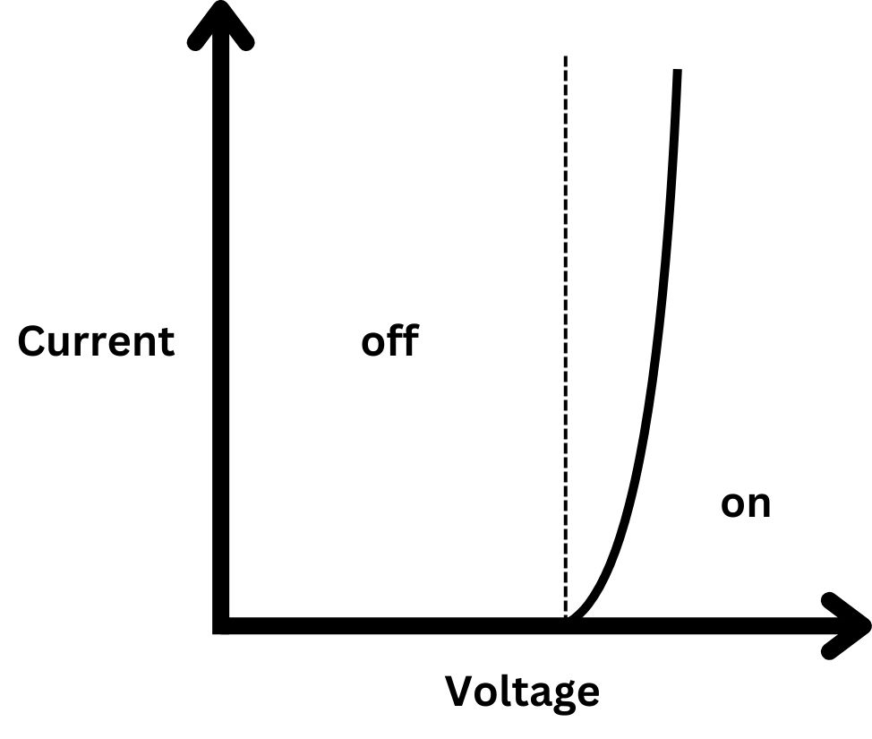
This curve cannot go up indefinitely, the LED stops working and is burned down. The manufacturer gives a safe current amount which we can use continuously and not worry about LED stopping working.
LED Colors and Materials
The color of light emitted by an LED depends on the semiconductor material used in its construction. Different materials have different bandgap energies, which determine the wavelength of the emitted photons and, consequently, the color of light.
Some common LED materials and their corresponding colors are:
- Gallium Arsenide (GaAs) - Infrared
- Aluminum Gallium Arsenide (AlGaAs) - Red
- Indium Gallium Nitride (InGaN) - Blue and green
White LEDs are typically produced by combining a blue LED with a phosphor coating that converts a portion of the blue light to longer wavelengths, resulting in a white light output.
My project used only red LEDs to make the power consumption lower.