Introduction to MOSFETs
MOSFET is a semiconductor device and an abbreviation for Metal-Oxide-Semiconductor Field-Effect Transistors.
Now, in this post we will mostly talk about MOSFET as an abstraction to an electrical switch. So we will not talk about how it works in detail, under the hood, but about some of its characteristics and appearance.
Electric switch
MOSFET is an electric switch, this means the output and input are of the same "type". We need this property to build a computer. The interesting thing is that this type does not have to be electricity as is the case with MOSFET, it can be mechanical motion or biological reaction.
If you look at a light switch, it is a switch but does not satisfy the property that input and output are of the same type. You would not be able to make a cpu out of light switches and lights because output of one light switch can not influence the other switch (because it accepts mechanical motion as input rather than light).
To make a computer out of it you would need a light sensor and an electric motor for example. This way input and output would be mechanical. Bear in mind this is a necessary but not sufficient.
Why electric
Now why should my computer be electric, why not mechanical? Indeed first computers were mechanical, but they were not without problems. If you have something moving it can break more easily, it needs lubrication, cannot be small and you need to somehow power it.
A wholly electrical switch is solid state and can be made really small. No moving means less breaking which means you can have more of them and thus have more powerful computer.
Appearance
You can find them in all shapes and sizes but I choose a through hole package:
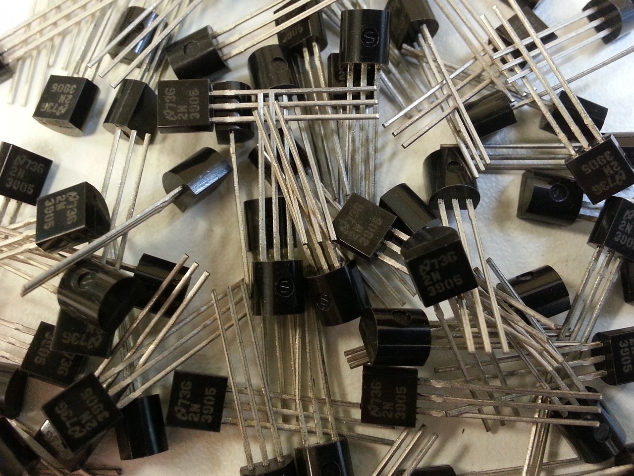
In the image above there are lots of MOSFETs, with each being around the size of your fingernail.
Connections
The connections and later graphs will be in respect to N type MOSFET, there is also P type but they are practically the same thing just with the polarity reversed.
So if I told you that MOSFET is an electric switch you would expect that it has one input pin into which current flows and one output one (current that entered has to exit). Now there also needs to be some way of controlling that turning on and off of a switch, so there is one extra pin (or two).
MOSFET has three pins and those are:
Schematic
As we did with the resistor we need some symbol to abstract away the details of MOSFET and enable us easier drawing of schematics:
So from top to bottom the pins are drain, gate and source.
Here is an example how we would wire it up (try pressing the switch to turn the MOSFET on and off):
So let's explain what is happening and why it is wired like that. MOSFET is a voltage controlled electric switch. Which means that it turns on (starts conducting electricity) when the voltage at gate is above a certain threshold.
We are simulating the changing of the voltage at the gate with a switch. When it is pressed the gate is directly connected to the positive terminal of the battery so MOSFET "turns on" (converts to a resistor of low resistance) and the current passes.
When the switch is not closed the gate is connected through 100k resistor to negative terminal of the battery. So the MOSFET turns off. If there were no 100k resistor the MOSFET would stay on for a bit more time, since the gate is a capacitor. We go through that in one of the next chapters. The 50 ohm resistor is there so that there is no large current going through the circuit. This could happen because when it is on, the MOSFET is of low resistance.
Characteristics
The strength of the electric field, and consequently the current flow, is controlled by the gate voltage. By adjusting the gate voltage, we can modulate the amount of current flowing between the source and drain, enabling the MOSFET to function as a switch or amplifier.
We will see the relationship in the next sub chapters:
Output
The output characteristic of a MOSFET depicts the relationship between the drain-source voltage (VDS) and the drain current (ID) for a constant gate-source voltage (VGS).
It shows how the drain current varies with changes in the drain-source voltage.
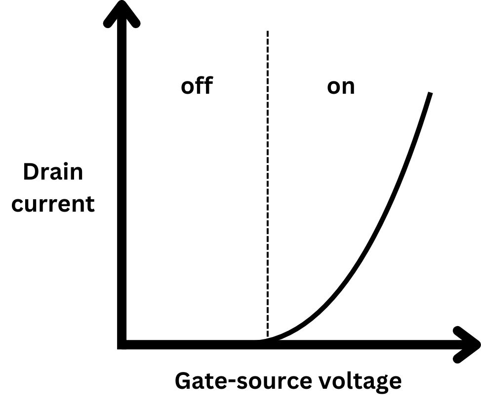
The current is around 0 before the voltage crosses a threshold. After it crosses the threshold the MOSFET is in "on" state. This is analogous of closing the light switch, the only difference is that this is more gradual. But if we restrict ourselves to digital values as input we will also get digital values as output.
One other nice graph to see is the MOSFET resistance:
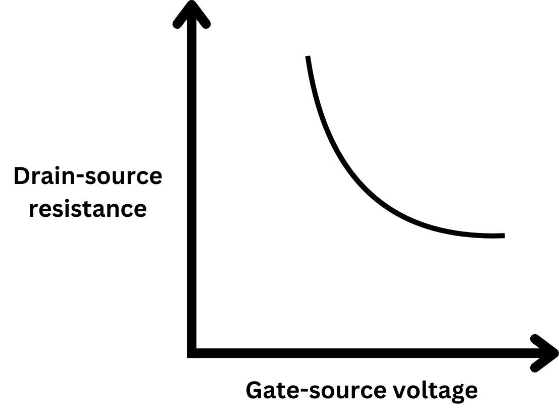
It shows the essence of MOSFET for our purposes. When the voltage at the gate is low it has high resistance, and when it is high the resistance is low.
It is also worth noting that resistance is high even if we have a small voltage on the gate and in the "on" state it is low even if we nudge the voltage up or down, so we can say that it a robust switch (for areas outside the transition area).
Transfer
The transfer characteristic of a MOSFET describes the relationship between the gate-source voltage (VGS) and the drain current (ID) for a constant drain-source voltage (VDS). It shows how the drain current varies with changes in the gate voltage.
We can find 3 distinct parts of the graph above:
- Linear Region (Triode Region): In this region, the gate-source voltage is above the threshold voltage, and the drain-source voltage is relatively small. The MOSFET operates as a voltage-controlled resistor.
- Saturation Region: In this region, the gate-source voltage is above the threshold voltage, and as we change the drain-source voltage, the current does not change. The MOSFET operates as a constant current source.
- Breakdown: All electrical insulators and semiconductors have an voltage they can endure. After that voltage they break down and allow current to pass.
There is also one more that is hidden:
- Cutoff Region: If you look at the definition of this graph, we say something something for some "constant voltage". If the voltage is below a threshold the graph is much simpler, current is 0 always.
MOSFET Parameters
So now that we have all the graphs we can define the following parameters that characterize the behavior and performance of a MOSFET:
- Threshold Voltage (VTH): The minimum gate-source voltage required to create a conductive channel between the source and drain.
- Transconductance (gm): The ratio of the change in drain current to the change in gate-source voltage, which determines the amplification capability of the MOSFET. This is analogous to resistance in resistors.
- On-Resistance (RDS(on)): The resistance between the source and drain when the MOSFET is fully on, which affects power dissipation and switching speed.
- Breakdown Voltage: The maximum voltage that the MOSFET can withstand before experiencing permanent damage or breakdown. This one is usually quite high for the transistor type I used in the build.